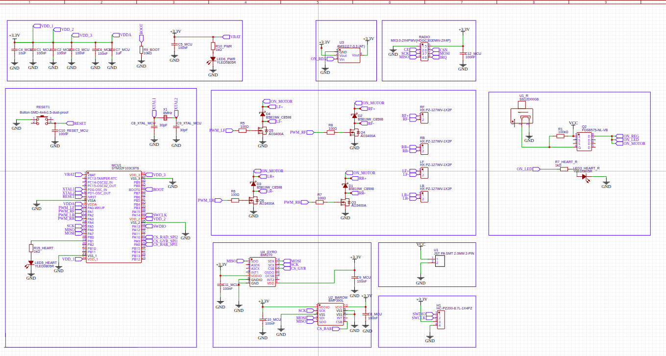
DIY Drone custom PCB.
A tiny drone and a remote to fly it, both on boards I designed. Still building it.
Previous version
Small, and all mine.
A tiny whoop-style FPV drone, about 10 cm across. I designed the flight controller myself in EasyEDA, and it goes in a 3D printed Firebird 720 frame with a bay of about 26 x 26.7 mm for the board.
In this version an STM32 runs it, and a BMI270 gyro and a BMP390 barometer track its tilt and height. Each of the four 720 brushed motors gets its own AO3400A MOSFET and flyback diode.
It runs off a 1S LiPo through a MOSFET power switch, and I program it over SWD with an ST-LINK.
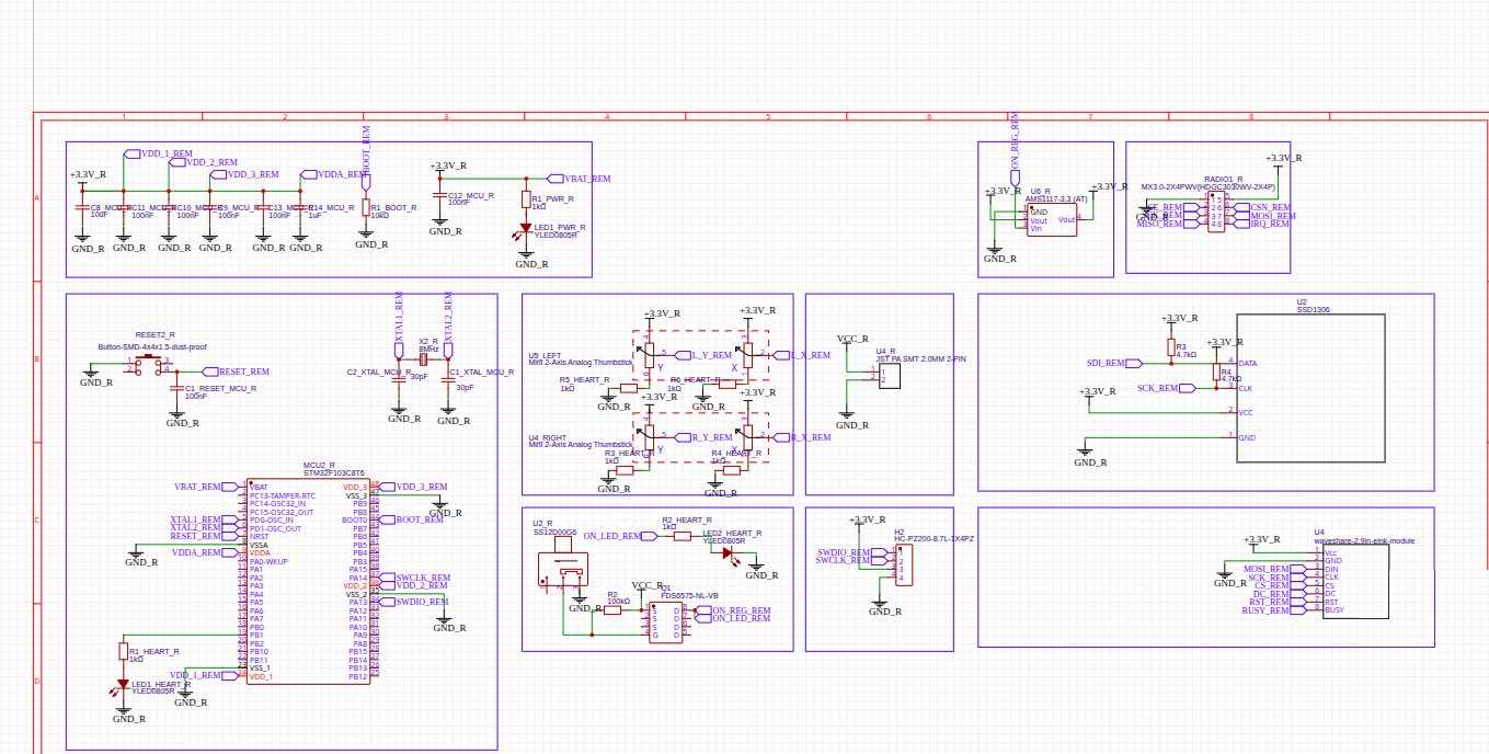 Previous version
Two sticks, two screens.
An STM32 reads two thumbsticks and drives two screens: a small SSD1306 OLED and a built-in 2.9 inch e-ink display.
This version talks to the drone over an NRF24L01 radio, and that's about to be updated too.
I want it to run Betaflight, which no longer supports the STM32F1 I picked. So the drone moves to an STM32F411 and an ExpressLRS radio.
- 01
New version
Redrawing the schematic around the STM32F411 and an ELRS receiver.
- 02
PCB
Laying out a board that fits the bay in the 3D printed frame.
- 03
Parts
Buying the components. JLCPCB assembles the STM32F411, since its pads sit under the chip.
- 04
Betaflight
A small config file maps my pins, then I bind the radio and tune it.
- 05
First flight
Then it finally flies.
- 06
Photos
Pictures and results go on this page as they happen.
So far it's taught me MOSFET switching, flyback diodes, decoupling, when to use SPI, I2C or UART, and to check firmware support before committing to a chip.